Pressure Die Casting Tool Design
Mold design in High Pressure Die Casting
November 28, 2017
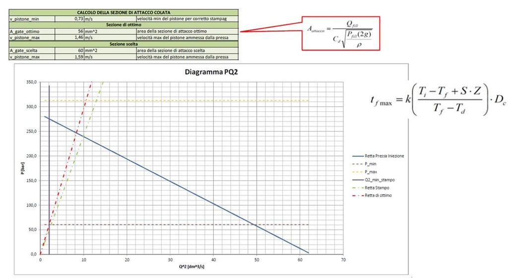
In this post we are going to fully describe the process of mold design for high pressure die casting. Before starting with the actual mold design it is necessary to verify the manufacturability of the piece with high pressure die casting technology. In this phase the practicability of the process should be judged from a dimensional and geometrical point of view. Because of this, it would be advisable for the manufacturer to make an arrangement with his client to elaborate the project within a co-design service, to find an agreement on the modifications of critical tolerances, on the geometry of the component and on the position of the die's parting lines. Once the manufacturability of the component has been verified, it is possible to move on with the actual mold design. The design of pressure die casting mold begins with the knowledge and the definition of the piece that is going to be casted. In order to deeply analyze the different design phases, it is necessary to reconsider the previously obtained data regarding the weight (or volume) of the component, its projection area towards the die opening, and the number of cavities needed. To calculate the number of cavities it's very important to consider hypothetical cycle time, number of pieces which have to be produced and cavities orientation on mold. It will be possible to choose between a single cavity mold or a multi-cavity mold. When considering a multi-cavity mold, it is necessary to keep in mind that not only the complexity of filling and ejection phases will increase, but also that the handling of the production process may be affected by cavities' disposition and dimensions of the products. An example of this can be found in logistics, since an higher number of impressions means a direct increased flow of material to move. The projection area identifies the theoretical surface that can be obtained by the projection of a cavity on the plan which is perpendicular to the mold opening direction. Projection area plays a fundamental role in the designing phase: from it depends the opening force generated by molten metal on die walls. Depending on shape dimension orientation, stronger or weaker forces will be applied in mold filling phase. An excessively strong force may bring to a material overflow, and thus to the formation of burrs on the product profile. If the forces are too strong compared to the closing force of the press, the result could be a non-compliant product or, in the worst case, an unfeasible process. In order to prevent this, the maximum force generated by molten metal in filling phase can be estimated. This force is equal to the product of the projection area, the maximum specific pressure of the machine and a pre-set safety factor. This factor is based on metal dynamic push. Its main function is to offer a wide margin to counter the moment of maximum pressure at the end of the filling process, usually called water hammer. At the end of the process machine transfers both static and dynamic force, leading to a pressure pick that must be absorbed by the closing force of machine itself. The closing force produced by the press depends on the press model and on the dimension of its stroke. The push of metal and the projection area are the core elements to consider during mold design. As stated above, the volume of the component is fundamental for the design of the mold. In addition to the total volume, it should be taken in account that massive components will suffer a greater shrinkage, caused by shrinkage rate increase, due to longer cooling times. Therefore the mold cavities should be sized accordingly. Once positions and dimensions of these elements are decided, it is possible to move on to the next phase. After completing the initial design of the mold, it is possible to proceed with a simulation of die filling by the use of semi-empirical models. These simulations are used to calculate the ideal modality of mold filling: depending on the function of the casted piece, the filling process may vary. For components with a structural role it is better to enhance mechanical resistance and compactness, while for aesthetic components it will be necessary to obtain the best surface finishing possible, thus avoiding any superficial porosity and internal air trapping that may escape afterwards, damaging the external surface treatment. By varying the filling time it is possible to alter these characteristics: the quicker the filling, the better the surface quality; on the contrary, a longer filling time at higher pressure will lead to a stronger, more resistant compound. After completing these analysis it will be possible to spot in advance the eventual issues in casting phase and therefore to intervene on the design, before building the die. To sum up, mold design for high pressure die casting begins from a manufacturability analysis, followed by a calculus of metal pushing forces and a study of channels position for injection, vents, and the necessary slides. Design and optimization of these channels can be done through the use of a simulation software to decide the ideal filling mode and to spot any possible issue. Once all of these phases are completed, it is possible to move on to the production of the designed mold. To always be up-to-date with the last news in die casting, subscribe to our blog.
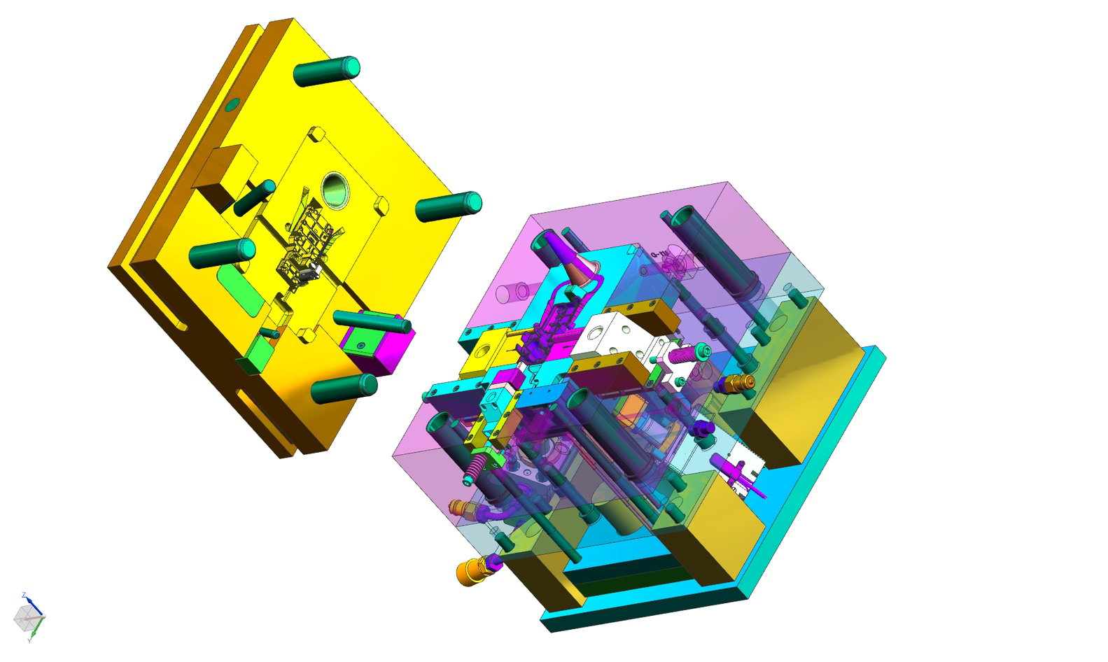
Preliminary Phase
In order to calculate the volume of the casting and the opening force we need to know the dimension of the component and the required number of cavities for each casting. These two data prove essential for studying the feasibility of the process.
The geometry of the component should include the drawing of the parting line. This line splits mold in two parts which allow mold opening and casting ejection. Component surfaces tilt depends on their position from parting line: surfaces have to be oriented in mold opening direction. Moreover, the geometrical tolerances of quotes, which can be found on the 2d model or can be indicated by the costumer, can be difficult to achieve due to the shrinkage caused by metal cooling. Quotes with identical tolerances can be more or less critical, depending on their nominal value: the higher the nominal value of a quote, the higher the difficulty to obtain the same value on the casting. This is called "manufacturing precision" and it is present in every technological process. Number of cavities
Projection Area
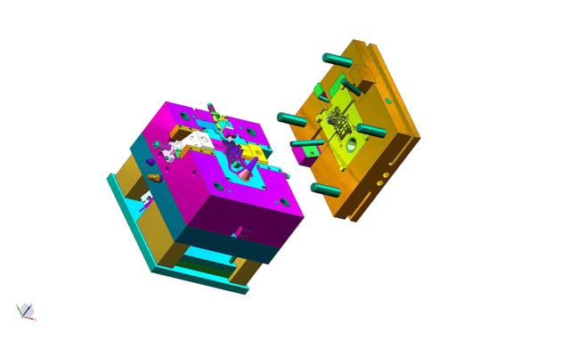
Volume and shape of the die
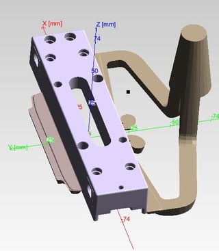
Moreover it is necessary to consider a number of variables that will determine the final size of the mold. Among these, the most prominent are the injection channels, the kind of die closing, the width of the runners and the presence of overflows.
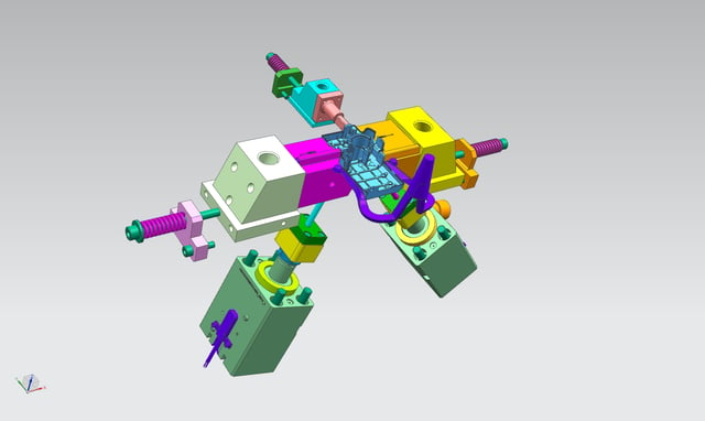
Simulation through semi-empirical models

Pressure Die Casting Tool Design
Source: https://www.bruschitech.com/blog/mold-design-in-high-pressure-die-casting
Posted by: voexill1984.blogspot.com

0 Response to "Pressure Die Casting Tool Design"
Post a Comment